
S++Current Density Distribution Measurement

 The browser own share function is also very useful~
Current Density Distribution Measurement in large fuel cells and fuel cell stacks

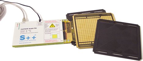
Measurement device of the type current scan lin for a 150cm² stack
Measurement data
The devices of type current scan lin allow:
+ detailed analysis of flow fields
+ detailed analysis of materials
+ optimization of fuel cells
+ fault diagnostics in fuel cells
+ resolution of about 7 x 7 mm
+ current range up to 2.5 A/cm²
+ temperature range up to 180°C
+ standard devices are available
+ special designs on request
With the current scan lin, the current density distribution can be measured with a high resolution and it offers a linear complexity. So it is also applicable in large fuel cells. It is connected via USB to any computer and easy to use.
In a fuel cell the local conditions differ, which leads to an inhomogeneous mass conversion resulting in an inhomogeneous current production. One of the keys to a deeper understanding of PEM fuel cells, DMFC and other electrochemical cells, is the measurement of the current density distribution. In large fuel cells this is important for a save and reliable operation as well as a high lifetime. Up to now the high complexity was a major problem.
Application
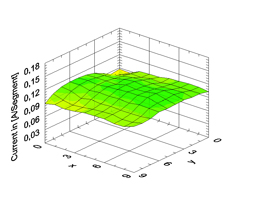
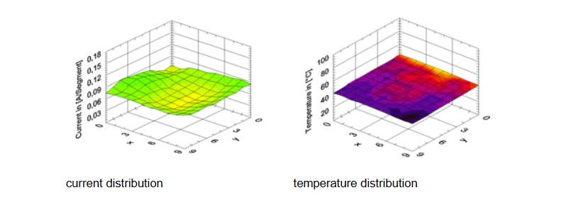
The device of type current scan lin shown befor has a resolution of 17 x 19 measurement cells and an active area of 150cm². It will be placed between the two halves of a bipolar plate at an arbitrary place in the stack. The pictures below show a typical current distribution and a temperature distribution.
Measurement Principle
The measurement cells of the devices ot type current scan lin are build up small transformers. This is shown in the following picture.
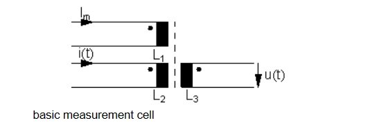
The permeability of a magnetic material is dependend on the magnetization and the temperature. The current Im, which has to be measured, flows through the coil L1 and causes a magnetization of the magnetic material (dashed line). An alternating current i(t), feed into L2, induces a voltage u(t) into the coil L3. This voltage depends upon the permeability of the magnetic material (dashed line). So it depends upon the current Im.
Single measurement cells are conducted in series, in rows and columns. This is shown in the following picture for example at 3 x 3 measurement cells.
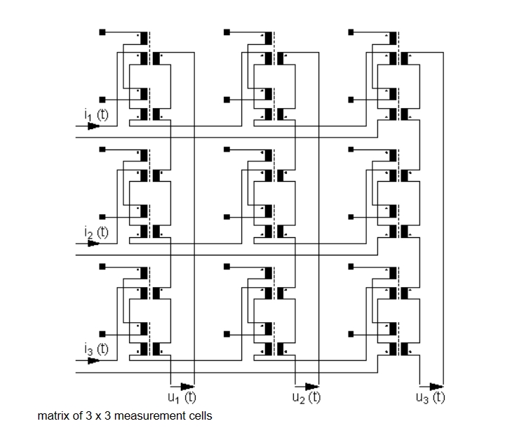
The alternating currents i1(t) to in(t) will be fed consecutively into the matrix to activate the rows 1 to n. At the columns the voltages u1(t) to un(t) will be acquired as measurement signals. The measurement cells, which are not activated by an alternating current, deliver nothing to the measurement signal. In general n² measurement points can be reached with 2 n wire pairs. So the complexity for connection wires, control and evaluation electronics is linear! This way, measurement devices for arbitrary large fuel cells can be built easily.
Available standard devices
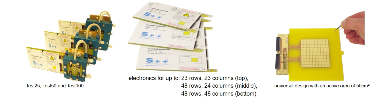
The following picture shows the standard devices Test25, Test50 and Test100 complete with 25cm², 50cm² and 100cm² single cell fuel cell and resistors to heat up the fuel cells.
Different electronics which are able to drive up to 48 rows and 48 columns are available. They also differ in the number of independent input channels, influencing the speed.
Also available with 50cm² and 100cm² is the shown universal design. Outside the active area with measurement cells and a restricted area for the conductor paths, arbitrary holes may be drilled.
Custom made devices
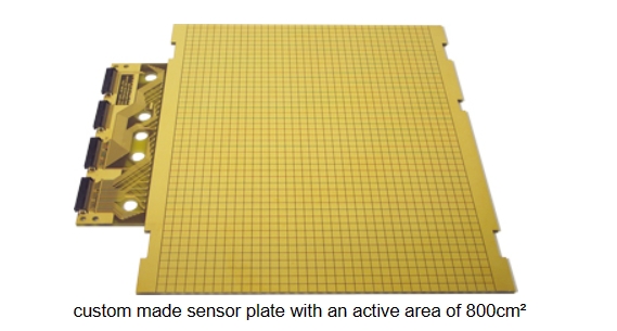
The above picture (by courtesy of Helion) shows a custom made sensor plate with an active area of 800cm² and 46 x 36 measurement cells. Nearly any design is possible. The minimal size of the measurement cells is 7 x 7mm. The maximal size is restricted by the current they have to measure and should not be much larger.
Current Density Distribution Measurement in large fuel cells and fuel cell stacks
Measurement device of the type current scan lin for a 150cm² stack
Measurement data
The devices of type current scan lin allow:
+ detailed analysis of flow fields
+ detailed analysis of materials
+ optimization of fuel cells
+ fault diagnostics in fuel cells
+ resolution of about 7 x 7 mm
+ current range up to 2.5 A/cm²
+ temperature range up to 180°C
+ standard devices are available
+ special designs on request
With the current scan lin, the current density distribution can be measured with a high resolution and it offers a linear complexity. So it is also applicable in large fuel cells. It is connected via USB to any computer and easy to use.
In a fuel cell the local conditions differ, which leads to an inhomogeneous mass conversion resulting in an inhomogeneous current production. One of the keys to a deeper understanding of PEM fuel cells, DMFC and other electrochemical cells, is the measurement of the current density distribution. In large fuel cells this is important for a save and reliable operation as well as a high lifetime. Up to now the high complexity was a major problem.
Application
The device of type current scan lin shown befor has a resolution of 17 x 19 measurement cells and an active area of 150cm². It will be placed between the two halves of a bipolar plate at an arbitrary place in the stack. The pictures below show a typical current distribution and a temperature distribution.
Measurement Principle
The measurement cells of the devices ot type current scan lin are build up small transformers. This is shown in the following picture.
The permeability of a magnetic material is dependend on the magnetization and the temperature. The current Im, which has to be measured, flows through the coil L1 and causes a magnetization of the magnetic material (dashed line). An alternating current i(t), feed into L2, induces a voltage u(t) into the coil L3. This voltage depends upon the permeability of the magnetic material (dashed line). So it depends upon the current Im.
Single measurement cells are conducted in series, in rows and columns. This is shown in the following picture for example at 3 x 3 measurement cells.
The alternating currents i1(t) to in(t) will be fed consecutively into the matrix to activate the rows 1 to n. At the columns the voltages u1(t) to un(t) will be acquired as measurement signals. The measurement cells, which are not activated by an alternating current, deliver nothing to the measurement signal. In general n² measurement points can be reached with 2 n wire pairs. So the complexity for connection wires, control and evaluation electronics is linear! This way, measurement devices for arbitrary large fuel cells can be built easily.
Available standard devices
The following picture shows the standard devices Test25, Test50 and Test100 complete with 25cm², 50cm² and 100cm² single cell fuel cell and resistors to heat up the fuel cells.
Different electronics which are able to drive up to 48 rows and 48 columns are available. They also differ in the number of independent input channels, influencing the speed.
Also available with 50cm² and 100cm² is the shown universal design. Outside the active area with measurement cells and a restricted area for the conductor paths, arbitrary holes may be drilled.
Custom made devices
The above picture (by courtesy of Helion) shows a custom made sensor plate with an active area of 800cm² and 46 x 36 measurement cells. Nearly any design is possible. The minimal size of the measurement cells is 7 x 7mm. The maximal size is restricted by the current they have to measure and should not be much larger.

cancel
Clear records
history record
Clear records
history record
A planned and systematic training and training activities carried out by enterprises to improve personnel quality, ability, work performance and contribution to the organization.

品牌认证
2970天
已认证
